Thermal design of a gas-fired air heater
The gas-fired air heater shown in the top figure is used in the food industry for heating up process air with a heating power of up to 3 [MW]. The cylindrical combustion chamber is enclosed by several sheet metal tubes. By these annular gaps, the flue gas flow and the process air flow are separated alternately. In addition, some of these tubes are equipped with helical sheets in order to guide the air flow.
Prior to the setup of a prototype with increased heating power, it should be checked by coupled thermo-fluid simulations whether the projected thermal efficiency and process air temperature will be achieved.
As an example, the mid figure shows the temperature distribution at the inner tube surrounding the combustion chamber and the spiral, which is welded to this tube. The maximum temperatures are located on the left side adjacent to the flame and at the right end of the tube, which is cooled less effectively by the process air.
The bottom figure shows the velocity distribution of the process air. Within the outermost annular gap, the cold process air flows helically from the right to the left. Within two additional annular gaps it flows to the right and back to the left, the latter again in helical manner. The highest flow velocities are observed near the left end of the innermost annular gap. Here the cross section is significantly reduced, the air temperature is maximal and the flow is spinning. The helical sheets prove to be very effective with respect to heat transfer. However, they produce significant pressure loss.
After optimizing the lengths and diameters of the cylinders, the gap widths and the helix angles the gas-fired air heater achieved all requirements regarding thermal efficiency, process air temperature and pressure loss.
Our specialists are always at your disposal to flexibly respond to your respective requirements and wishes.
Dr. Michael Elbs, Managing Director

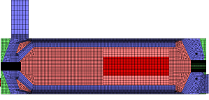
Thermo fluid model of a gas-fired air heater (cutting view) with connection pipes for gas and process air
red: area filled with flue gas
blue: area filled with process air

Temperature distribution at the inner tube and the attached helical sheet for guiding the process air
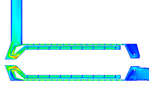
Velocity distribution of the process air (cutting view)