Shock analysis of a CFRP drive shaft
The strength against shock events of a ship power unit including a CFRP drive shaft should be verified already at the design phase.
The 1st picture shows the structure of the power train. Link elements with elastic rubber sockets are used to compensate axial, radial and angular displacements.
A suitable FEA model of the drive shaft was set up to perform the shock analyses. Besides the CFRP tube, the FEA model includes in particular the link elements, the connection flanges and the hubs of the CFRP tube.
The 2nd picture shows exemplary a detailed view of a link element and its adjacent components. Additionally, an MBS model of the motor unit and its bearings was included.
Several shock events were analysed considering the rotation of the shaft. For each event the time-dependent displacements at the propeller and at the bearing base points of the motor unit were prescribed. In addition to the rotation of the shaft, the static drive torque was included in the ABAQUS/Explicit simulations of each shock event.
The results of the shock simulations show that the occurring stresses of all drive shaft components especially the CFRP tube are well below the allowable strength limits. Also the stresses of the link elements are well below the according strength limits.
Additionally, the time-dependent displacements of the drive shaft close to existing constrictions were evaluated.
Our specialists are always at your disposal to flexibly respond to your respective requirements and wishes.
Dr. Michael Elbs, Managing Director

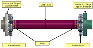
Total view of the CFRP drive shaft
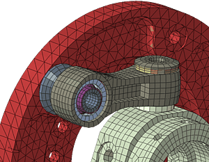
FEA model – detailed view of a link element with adjacent hub and connection flange
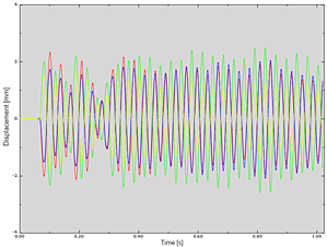
Vertical displacement at the bearings of the motor unit applying a shock event in transversal direction