Determining the flight path
The flight path of a passive flying object should be determined already in an early design stage. Its outer contour should be adjusted in order to match the aerodynamic requirements.
For this purpose, a CFD model of the flying object was created. It was used for flow simulations applying various approach velocities and angles. A primary result is the velocity distribution around the flying object as shown in the top figure for instance.
The pressure distribution as shown in the mid figure is integrated over the closed surface of the flying object in order to obtain the aerodynamic drag and the buoyancy force as well as the resulting torques acting on the flying object due to the flow forces.
Characteristic maps of the resulting forces and torques depending on the approach velocity and angle are created. This data is used for succeeding MATLAB/Simulink simulations in order to determine the flight path of the flying object. The block diagram of the applied Simulink model is shown in the bottom figure.
These flight path simulations show that the outer contour and the location of the center of gravity are the main parameters determining wether the flight path is stable or unstable. In the case of an unstable flight path, the flying object tends to tailspin and twirl around.
By a targeted optimization of the outer contour and of the location of the center of gravity, stable flight paths could be achieved for a wide range of launching angles.
Our specialists are always at your disposal to flexibly respond to your respective requirements and wishes.
Dr. Michael Elbs, Managing Director

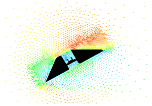
flow around the flying object
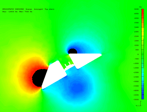
relative static pressure
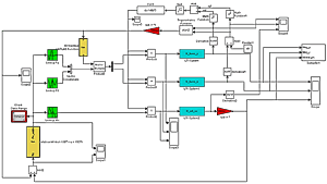
MATLAB/Simulink model for determining the flight path